
A awoke this morning with a sore neck and shoulders - Lego-fatigue is real. I sat down at 1800 (6pm) to resume my Landrover Defender build and at 0010 (12:10am) was still going - Hence the sore neck and shoulders.
I completed phase-2 of the build with all parts present and accounted for. There was a moment of panic towards the end when I thought one piece was missing however it was under my lego-snack bowl - Mandatory lego-sesh equipment you know - Snacks I mean.
Alright, I'll be totally honest; There were two moments of panic...But more about the second later.
Here you can see the first part of last night's build; The front axle and independent suspension. The black rod protruding from the front is a drive shaft.
This stage of the build sees the front of the vehicle complete however it happens in stages - A few sub-assemblies come together to complete it. It is also the phase where the front and rear of the vehicle are married up together.
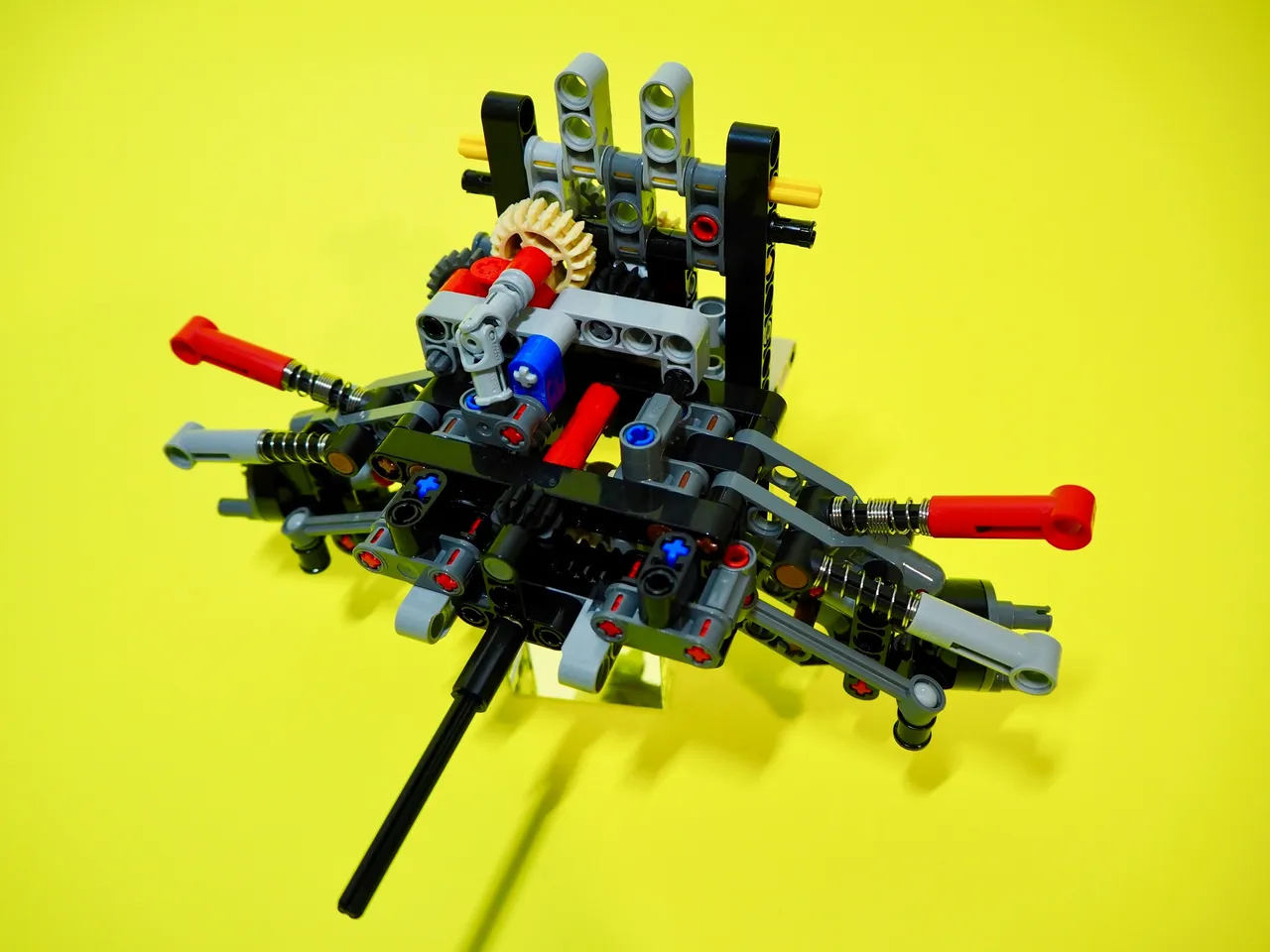
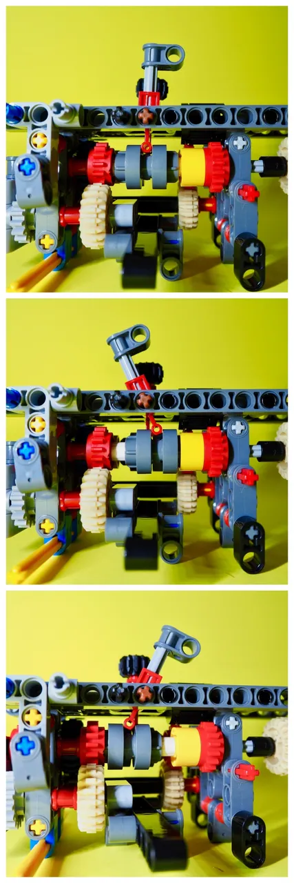
One of the coolest features of this build is all the moving parts; It adds to the complexity of build, and puts a lot of emphasis on getting tolerances right, but when parts come together and start moving - Well, it's very cool. Below you can see the engine which has been built upon the sub-assembly in the main picture above.
The camshaft, which is that assembly I've separated off in the below left image, connects to the drive shafts and makes the pistons in the engine move. It's ingenious engineering.
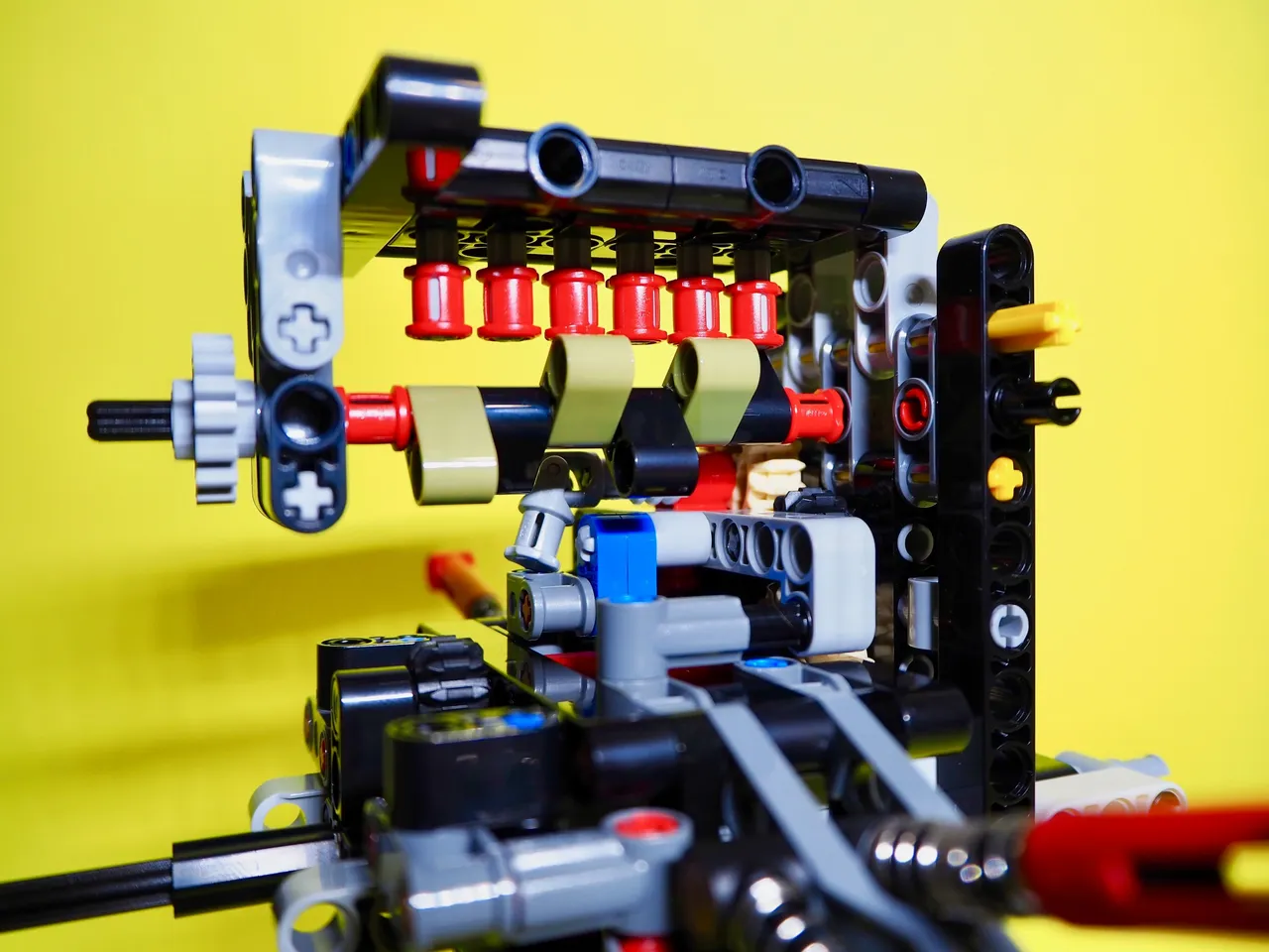
The camshaft before and after fitment. As it turns the elongated pieces raise or lower the pistons in the engine. From the top the pistons move and make it look like the engine is actually running. Yep, cool AF!
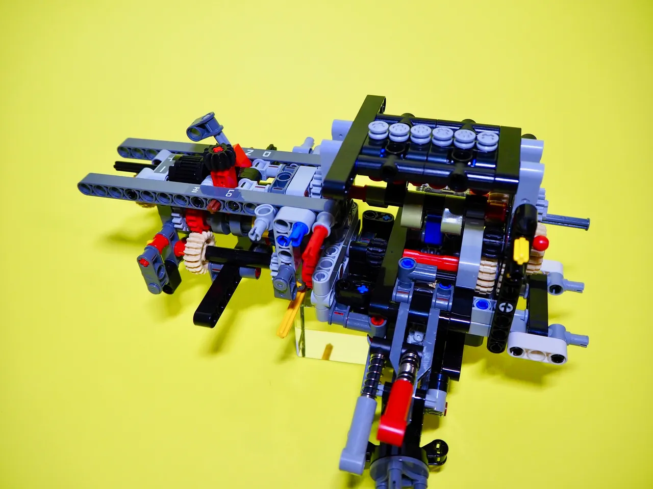
From here I put the front-end/engine assembly aside and got to work on the gear-selector and centre-console section which would eventually drop in behind the front-end assembly and on top of the gearboxes.
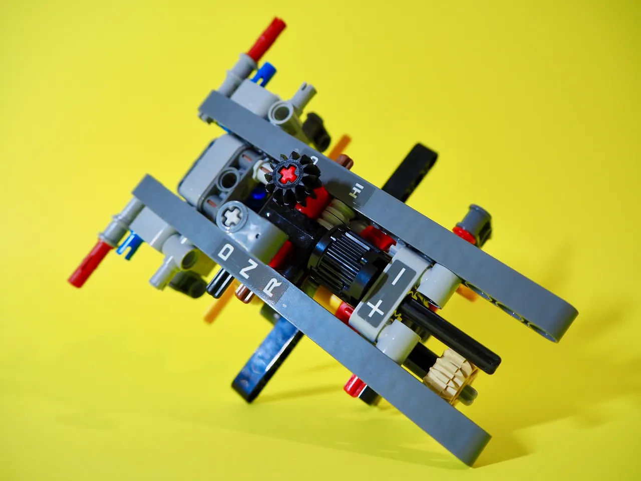
The console section is shown above. It has drive, neutral and reverse options plus high and low range selector as well - The lever with the black cog-selector on the top. The cool thing is, that as they are shifted, they actually change gears in the gearbox!
The image below shows a close up of each position from neutral at the top, drive in the middle and reverse at the bottom. You'll note that grey piece sliding back and forth depending on the gear selected. The high range/low range selector on the other side works the same. As you can imagine, getting the tolerances right within the inner-workings of the gearboxes is important. Fortunately mine works like clockwork.
Here you can see I've mated the console/selector section with the front-end/engine/suspension assembly. If only making real cars was this easy. As each section is brought together it is retained by push-in retainers which provide rigidity and strength to the vehicle - Important due to the size and function of this vehicle. This image also shows the little pistons of the engine - Those 6 round grey things at the top of the engine - These are the things the camshaft works when turning.
From here, the front and rear assemblies are joined together - A big moment. It's a little tricky as there are many drive-shafts and cogs that need to come together perfectly and some twisting, turning, lifting and jiggling is required - Plus some luck. Again, mine came together well and I felt a deep sense of satisfaction as the vehicle started to look like a vehicle rather than a combination of random parts.
At this stage all the drive-shafts need connecting and this is where panic number two happened.
I had flipped the vehicle upside down to connect the main drive-shaft which is an extension of the one sticking out of the assembly in the very first image. It connects from the very front all the way back into the differential in sections that are joined bit by bit. My problem arose when I was trying to push it into place with the shaft that connected directly to the differential.
Whilst pushing on the one I needed to connect into place and holding the one already in the differential I accidentally pulled the drive shaft out of the differential!
Simple matter of pushing it back in? Well no, not really.
The diff is made up of a housing and three individual cogs with the drive-shaft running through the middle of the central one. Now I'd pulled that shaft out the cogs collapsed. Yeah, I know. Fuckety fucking fuck!
The problem is that the differential, and assembly around it, is one of the very first parts built in this set; Pulling it out to fix it would mean taking the front end off, which I'd just connected, and completely pulling the rear apart. Completely. I say again...Fuckety fucking fuck!
What did I do? Well, I didn't spazz out although I wanted to. I went off to the bathroom, grabbed a few sets of tweezers and some toothpicks from the kitchen and set to work trying to align the cogs in the differential whilst getting the rear drive-shaft [sometimes called a prop-shaft] into place.]
Just so you know, in case you don't...The differential [in a vehicle] changes the direction of drive from the engine. Basically, the power comes out of the engine, through the gearbox and to the rear wheels via the drive-shaft which spins in turn with the transmission/gearbox. It spins left to right or right to left depending on if the car is going forwards or backwards. To make the wheels turn the drive needs to go forward or backwards so it needs to be converted to do so. The cogs in the differential do that. No drive shaft means no drive to the rear wheels.
Anyway, it worked out. I managed to get it back together and working - Only took me 30 minutes. I had toothpicks holding things at particular angles, tweezers and fingers going every which way, but it worked. [Insert huge sigh of relief here.]
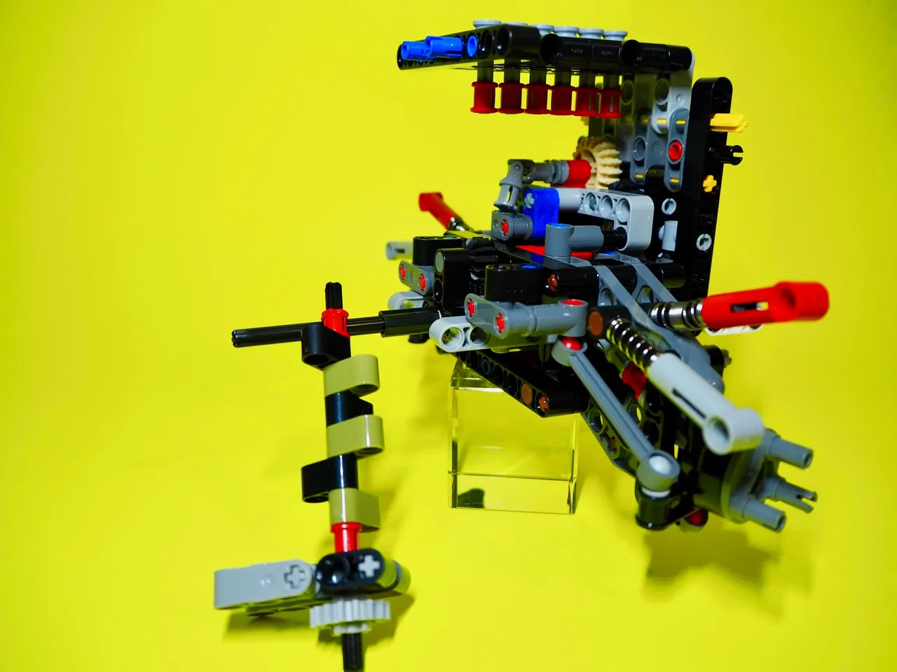
Here's the vehicle at the end of my 6-hour Lego-sesh. As you can see it sort of looks like a vehicle now. The engine has most of its detail added, the dashboard and seats are in and most of the internal moving parts are fitted including the working-winch at the front end.
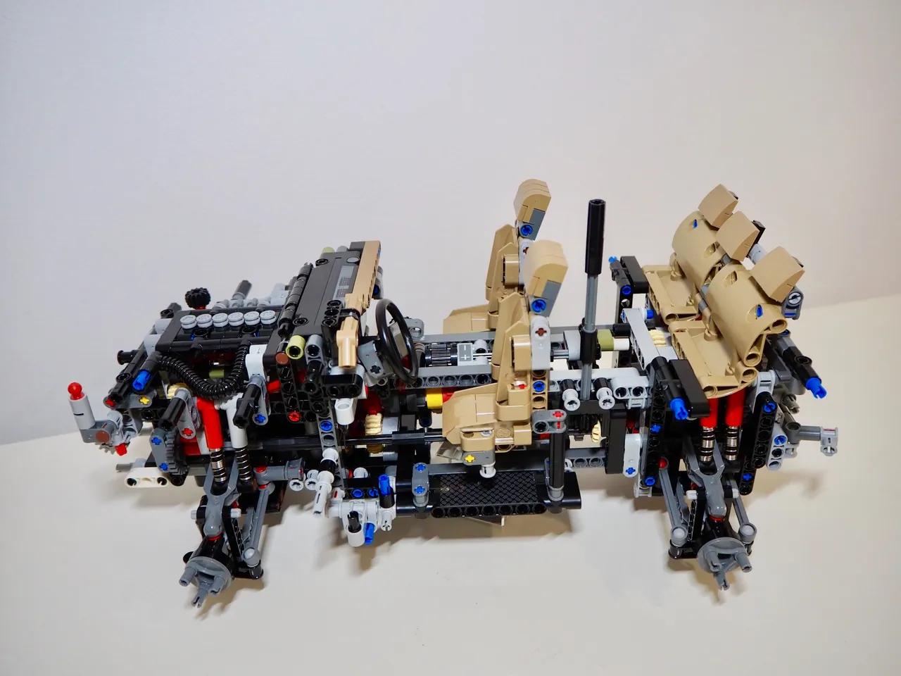
(Above) This is a big model, some 45cm long, with a lot of detail. See that shaft running upwards from behind the drivers-side seat? That's the shaft that will eventually connect with a little knob on the roof which will allow me to steer the vehicle once complete.
(Below) Here you can see the front of the vehicle. I took this to show the winch mounted at the front. The mechanism to operate it is at the left of this image but it's difficult to see. Once complete the knob to wind the winch in will be under the bonnet (hood) of the vehicle but that part of the build comes later.
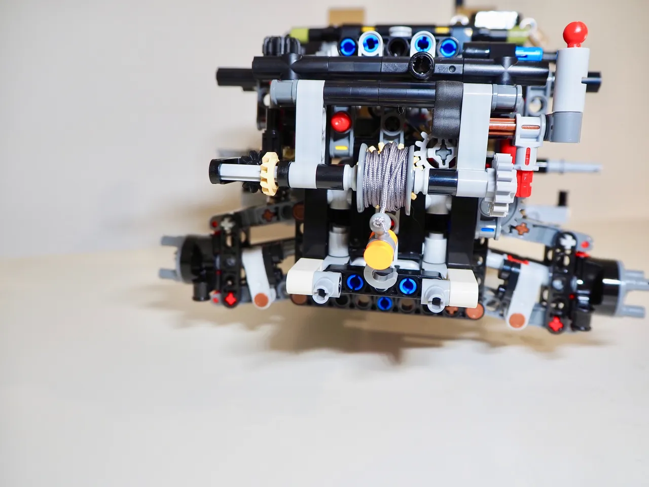
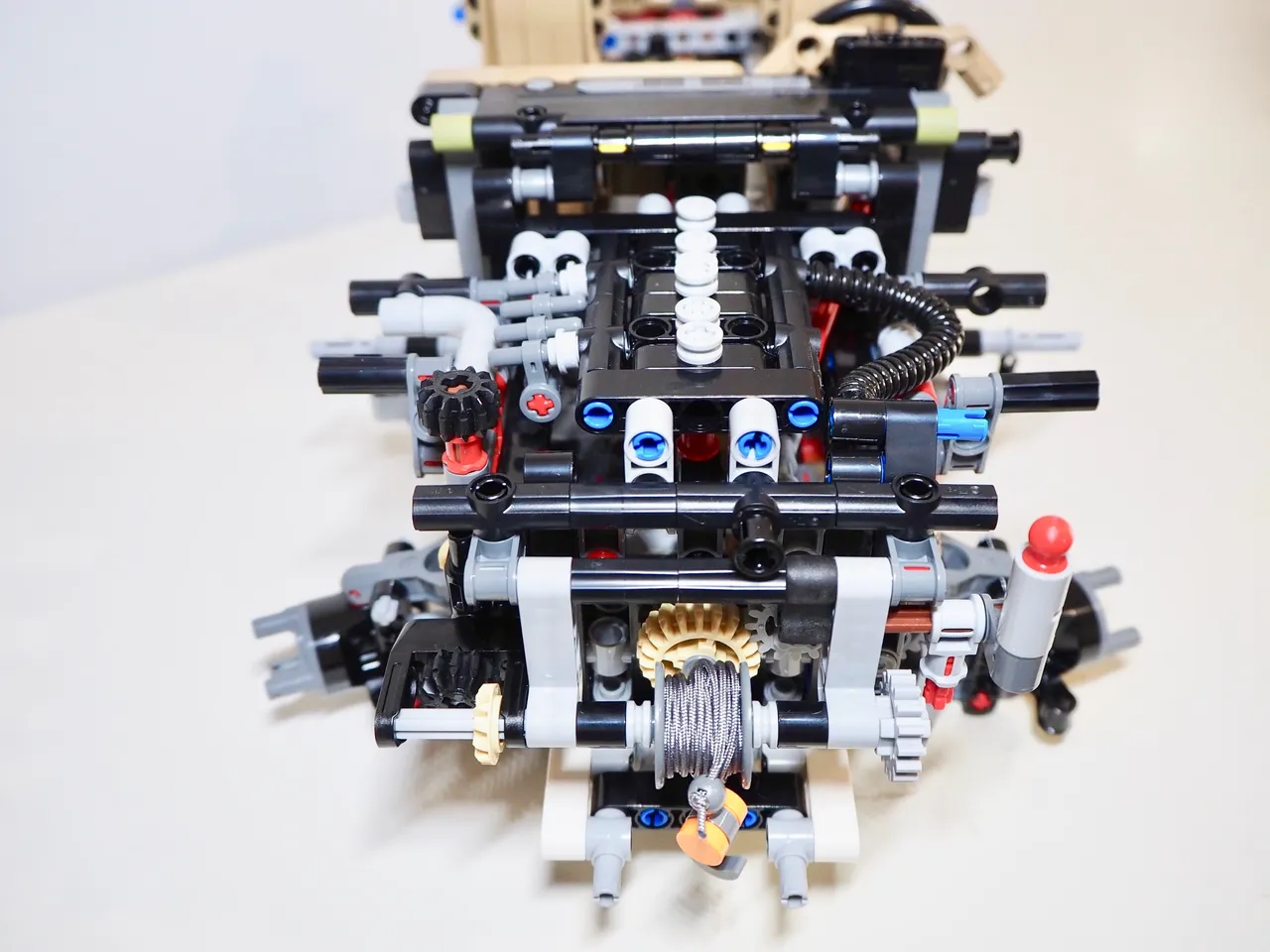
(Above) This image shows the winch mechanism a little better. On the left at the very corner you can see the mechanism housing and the horizontal black cog connected to the vertical cream-coloured one.
Phase two is complete and shortly I'll be starting phase three and obviously then the fourth and final stage. I believe it will get more difficult to show the inner-workings of the vehicle as the rest gets assembled so hopefully my photos are doing it justice now. I'm not much of a photographer and due to the size of the model it's now bigger than the backgrounds I use to shoot it - Hence the change from yellow back to white. I think I'll have to start taking it outside to get decent pictures from now.
Anyway, it's time to rest my weary old bones; Like I said earlier, Lego-fatigue is real.
Stay tuned.
Design and create your ideal life, don't live it by default
Discord: @galenkp#9209 🇦🇺